
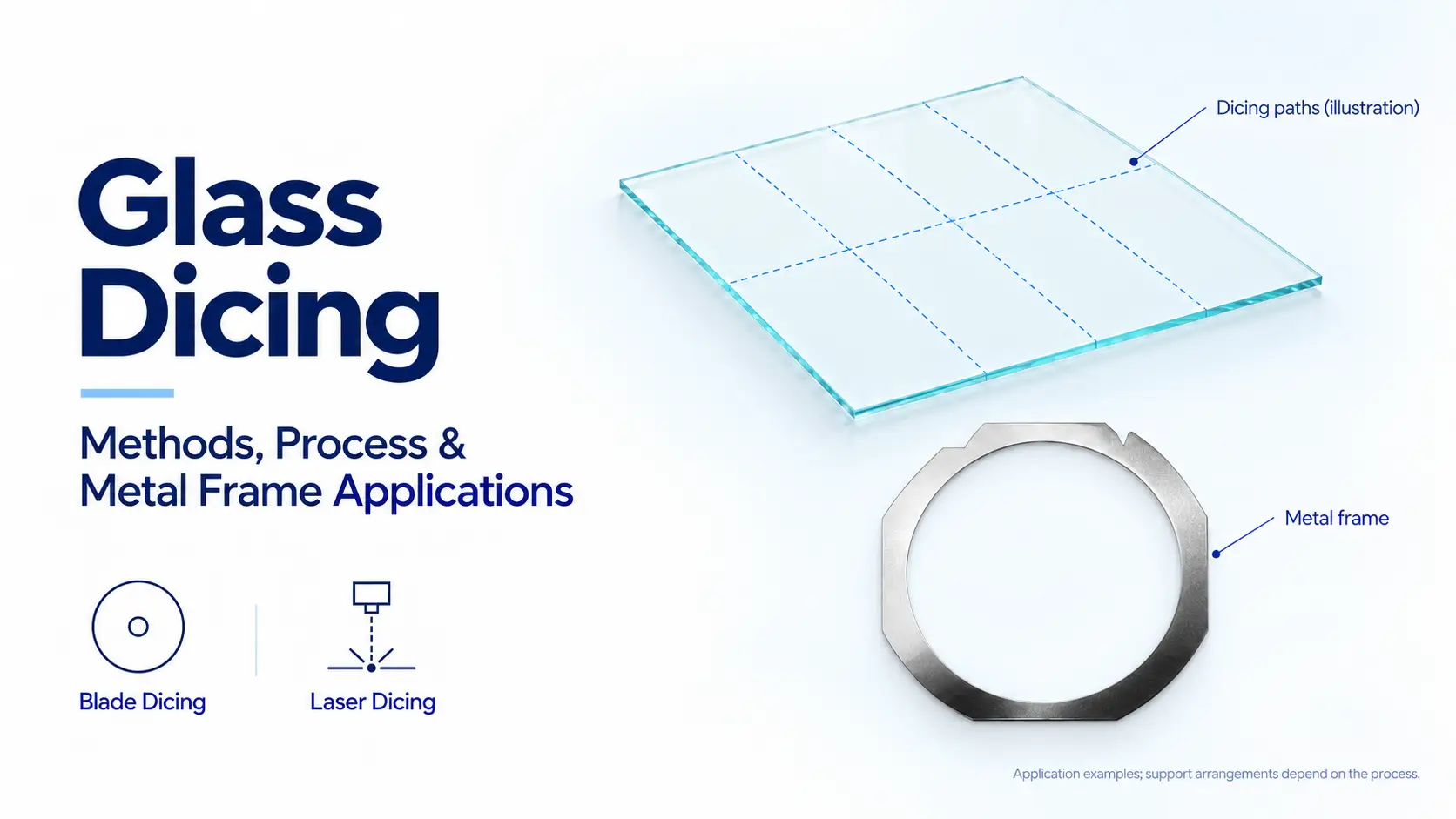
What Is Glass Dicing? Cutting Methods, Process and Metal Frame Applications
Glass dicing is the precision separation of a glass substrate into smaller components. It is used in manufacturing applications where part dimensions, edge quality and handling conditions need to meet defined requirements.
The process involves more than cutting through glass. The substrate needs suitable support during processing, and the separated parts need a practical way to move through inspection, removal and transfer.
At YJ Stainless, our role is to manufacture the metal frames used in tape-mounted configurations. We work from equipment requirements and customer drawings to evaluate frame geometry, dimensions, thickness and additional machining. These frames support the dicing tape and connect the workpiece assembly with the equipment’s loading and handling system.
This guide explains the main glass dicing methods, the role of tape and frames, and the factors that connect cutting quality with workpiece handling.
Where Is Glass Dicing Used?
Glass dicing is relevant to precision glass components used in optics, electronics, sensors and related manufacturing applications.
Workpieces may include individual glass substrates, glass wafers or bonded structures. For example, Fraunhofer ENAS’s dicing capabilities include glass and bonded silicon–glass and glass–glass wafers.
The appropriate process depends on the material and finished component. Substrate thickness, coatings, part layout and edge requirements can all influence the choice of cutting and support methods.
Here, “glass dicing” refers to precision substrate processing. It has different equipment and handling requirements from general architectural glass cutting.
What Are the Main Glass Dicing Methods?
Blade dicing and laser processing are two important approaches. They act on glass differently and may require different arrangements for cleaning, separation and handling.
1. Blade Dicing
Blade dicing uses a rotating abrasive blade to remove material along a defined path. Depending on the process, the blade may cut through the substrate or make a partial-depth cut for a later separation step.
Blade selection and cutting conditions need to suit the glass being processed. Cooling, debris removal and workpiece support are also part of the overall setup.
For difficult-to-process materials, some systems offer ultrasonic-assisted blade dicing. DISCO’s ultrasonic dicing description includes glass and optical components among its applications. This is an equipment-specific processing option rather than a requirement for all glass substrates.
2. Laser Dicing
Laser processing uses focused optical energy to act on the glass. The term covers different mechanisms, so a laser operation does not always produce the same workpiece condition.
Some processes remove material by ablation. Others create a modified region or a defined path that is followed by a separate breaking or separation operation.
Hamamatsu’s thin-glass micromachining examples distinguish laser cutting, scribing and drilling. Its examples also show why a demonstrated result needs to be understood in the context of the particular glass and laser system.
The comparison should include how the glass is processed and whether another step is needed to separate the parts.
Blade and Laser Glass Dicing: Key Differences
| Comparison | Blade Dicing | Laser Processing |
|---|---|---|
| Processing mechanism | A rotating abrasive blade removes material | Focused laser energy removes or modifies material, depending on the technique |
| Tool contact | The blade contacts the workpiece | No cutting blade contacts the workpiece |
| Separation | May involve a full cut or partial-depth processing | May complete cutting or require a later separation step |
| Process considerations | Blade condition, cutting load, cooling and debris removal | Glass–laser interaction, processing path and separation requirements |
| Workpiece support | Selected to match the substrate, tape system and equipment | Selected to match the specific laser process and downstream operations |
Neither method is automatically the best choice for every glass product. A useful comparison considers the same glass, finished-part requirements and completed processing stages.
How Does a Glass Dicing Process Work?
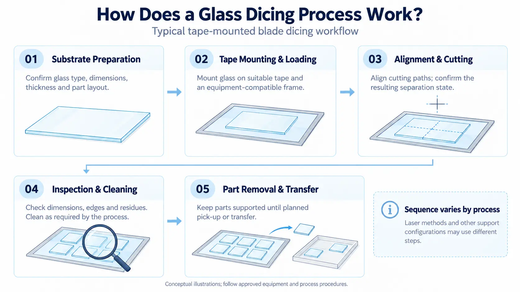
A typical tape-mounted blade dicing workflow includes preparation, mounting, alignment, cutting and downstream handling. Laser processes and other support configurations may follow different sequences.
1. Substrate Preparation
The starting information includes the glass type, dimensions, thickness, surface structure and intended part layout.
These details help the process team evaluate the cutting method, support arrangement and inspection requirements.
2. Tape Mounting and Frame Loading
The substrate is attached to suitable dicing tape and mounted on a frame compatible with the equipment. The assembly is then loaded for processing.
3. Alignment and Cutting
The equipment aligns the workpiece with the intended cutting paths. Processing then follows the selected method.
The workpiece state after this stage matters: it may be fully separated, partially cut or ready for an additional separation operation.
4. Inspection and Cleaning
Parts are evaluated against the applicable drawing and acceptance requirements. Inspection may cover dimensions, edge condition, separation and surface residues.
Cleaning requirements depend on the material, process and subsequent operation.
5. Part Removal and Transfer
Separated components may remain on tape until inspection or pick-up, or they may be transferred to another carrier.
The frame and handling arrangement need to support the planned transition between these stages.
What Do Dicing Tape and Metal Frames Do?
Dicing tape and metal frames have different functions.
The tape provides adhesion to the substrate and can retain separated parts in their arrangement. The frame supports the tape and interfaces with equipment loading, clamping and handling systems.
DISCO’s tape frame product information describes frames for holding wafers or other workpieces during dicing. Its range includes stainless steel frames and configurations for square workpieces.
A frame is therefore a supporting component, not the cutting tool. Its suitability depends on both the workpiece arrangement and the equipment interface.
Does Every Glass Dicing Process Need a Frame?
No. Some equipment configurations use tape frames, while others accommodate workpieces through different chuck or fixture arrangements.
For example, ADT’s glass dicing equipment range includes configurations described for use with a frame and others without one.
Does the Frame Need to Match the Glass Shape?
Not necessarily. A square substrate may fit within a frame whose external shape is determined by the machine.
Frame selection considers the substrate layout, internal opening, tape attachment area and equipment interface together. The finished component’s outline alone does not determine the frame shape.
What Affects Glass Dicing Quality?
Glass dicing quality is evaluated against the finished product’s requirements. Relevant characteristics may include:
- Dimensions and cut position: Whether the separated parts meet the drawing.
- Edge condition: The extent of chipping, cracks or other edge defects.
- Surface condition: Residues or contamination relevant to downstream use.
- Separation and handling: Whether components can proceed through inspection, removal and transfer as intended.
These outcomes can involve several interacting factors. A frame change alone does not establish that a cutting-quality issue has been resolved.
Where frame deformation, dimensional mismatch or loading problems are identified, a replacement or design adjustment may be appropriate. The relationship to the observed defect still needs to be evaluated by the equipment and process team.
How We Support Glass Dicing Applications at YJ Stainless
At YJ Stainless, we help customers obtain metal frames that match their glass dicing equipment and workpiece layouts. We offer custom frame manufacturing, additional machining, identification marking and existing-frame replacement.
Our metal frame product range provides a starting point for reviewing available designs. For applications requiring a different opening, thickness or external profile, we can evaluate manufacturing options from customer drawings.
1. Custom Frame Geometry, Openings and Thickness
The frame opening needs to accommodate the glass substrate layout and tape attachment area, while its external profile and thickness must suit the equipment’s loading arrangement.
We review these requirements together when assessing a custom design. Our Square Wafer Frame TJF-C is one example of our custom frame offering.
For a particular glass dicing application, your equipment and process team confirms the required interfaces. We evaluate how to manufacture the frame to the agreed drawing.
2. Additional Machining and Identification Marking
Some designs include machined features specified for equipment positioning or handling. We can assess these details alongside the frame’s material and dimensional requirements.
We also offer laser identification marking for part numbers, serial codes and other specified information. These markings help distinguish similar-looking frames used for different glass products or equipment configurations and connect them with your own inspection and maintenance records.
Our frame customization services describe the available machining and marking options.
3. Existing-Frame Replacement and Design Changes
For an existing-frame replacement, we can review the original drawing and required specifications to evaluate manufacturing.
If the glass dimensions, substrate layout or equipment have changed, we can also discuss revised openings, thickness or external geometry. Confirming these changes helps establish whether you need a direct replacement or a modified frame.
Whether the requirement is a new design or a replacement part, our role is to manufacture the supporting frame specified for your glass dicing setup.
Conclusion: Connect Glass Dicing with the Right Support Components
Glass dicing combines cutting with workpiece support, separation and downstream handling. The chosen method influences how the glass is processed, while the equipment configuration determines the required support components.
At YJ Stainless, we contribute through metal frame manufacturing and customization. From frame geometry and openings to additional machining and identification marking, we help customers produce the supporting component specified for their equipment.
Whether you need a new custom frame or an existing-frame replacement, contact us with your drawing and equipment interface requirements to discuss manufacturing options.
FAQs
1. Is glass dicing the same as glass cutting?
Glass cutting is a broad term. Glass dicing generally refers to precision substrate separation into smaller components, often with defined dimensional, edge-quality and handling requirements.
2. Can glass be processed on a wafer dicing machine?
Some dicing machines support glass as well as other substrate materials. Suitability depends on the machine configuration, cutting tool or laser process, workpiece dimensions and support arrangement.
3. Is laser dicing always better than blade dicing?
No single method is best for every application. The comparison depends on the glass, part geometry, quality requirements and complete processing sequence.
4. What does YJ Stainless provide for glass dicing applications?
We manufacture and customize metal frames for configurations that use this type of support. We can evaluate frame geometry, dimensions, thickness, additional machining and identification marking against your drawings.
5. Can you manufacture a replacement for an existing frame?
We can review your existing drawing and specifications to evaluate replacement-frame manufacturing. If the equipment or intended use has changed, those differences can be considered before the manufacturing specification is agreed.


